
- English
- Español
- Português
- русский
- Français
- 日本語
- Deutsch
- tiếng Việt
- Italiano
- Nederlands
- ภาษาไทย
- Polski
- 한국어
- Svenska
- magyar
- Malay
- বাংলা ভাষার
- Dansk
- Suomi
- हिन्दी
- Pilipino
- Türkçe
- Gaeilge
- العربية
- Indonesia
- Norsk
- تمل
- český
- ελληνικά
- український
- Javanese
- فارسی
- தமிழ்
- తెలుగు
- नेपाली
- Burmese
- български
- ລາວ
- Latine
- Қазақша
- Euskal
- Azərbaycan
- Slovenský jazyk
- Македонски
- Lietuvos
- Eesti Keel
- Română
- Slovenski
- मराठी
- Srpski језик

CAT Excavator 374D&390D Hydraulic Pump Control (output Flow)
Pump control (output flow) - adjustment
If the flow test results differ greatly from the technical specifications, adjust the pump output flow.
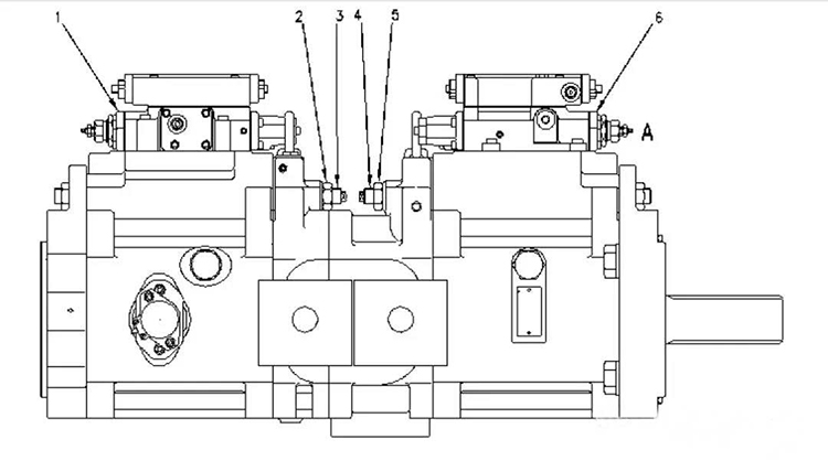
Photo 1
Front view of main pump
(1) Rear pump regulator
(2) lock nut
(3) Adjusting screw
(4) Adjusting screw
(5) Lock nut
(6) Front pump regulator
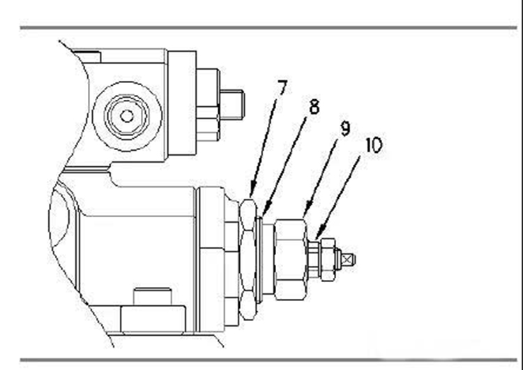
photo 2
(A) view
(7) Lock nut
(8) Adjusting screw
(9) Lock nut
(10) Adjusting screw
Adjustment of output flow under stable power control
Note: The main pump flow is adjusted by adjusting the rear pump regulator (1) and front pump regulator (6) under stable power control.
Perform the following steps to complete the first phase of adjustment.
A. Loosen the lock nut (7).
B. Turn adjusting screw (8) to the correct technical specifications.
Note: Increase the flow rate by turning the adjusting screw (8) clockwise. Reduce the flow rate by turning the adjusting screw (8) counterclockwise. At a system pressure of 20,600 kPa (3,000 psi), the adjusting screw (8) changes the flow rate by approximately 25 L/min (6.6 US GPM) every quarter turn. The flow rate change was approximately 12 L/min (3.2 US GPM) at a system pressure of 31,400 kPa (4,550 psi).
C. Tighten lock nut (7) until torque 155 ± 20 N·m (115 ± 15 lb ft).
2. Perform the following steps to complete phase 2 adjustment: 1.
A. Loosen the lock nut (9).
B. Turn adjusting screw (10) to the correct technical specifications.
Note: The flow rate is increased by turning the adjusting screw (10) clockwise. Reduce the flow rate by turning the adjusting screw (10) counterclockwise. At 31400 kPa (4550 psi) system pressure, the adjusting screw (10) changes the flow rate by approximately 28 L/min (7.4 US GPM) every quarter turn.
C. Tighten the lock nut (9) until torque is 120 ± 20 N·m (90 ± 15 lb ft).
Note: Any change in flow per full turn of the adjusting screw should be used as a reference only. Be sure to use a flowmeter to adjust pump flow.
Adjust the maximum output flow of the pump
1. To adjust the maximum output flow of the front pump, loosen the lock nut (5).
2. Reduce the maximum output flow of the pump by turning the adjusting screw (4) clockwise. Increase the maximum output flow of the pump by turning the adjusting screw (4) counterclockwise. Adjusting screw (4) Change the flow rate by about 8 L/min every quarter turn (2.1 USgpm).
3. Tighten the lock nut (5) until torque is 235 ± 20 N·m (175 ± 15 lb ft).
4. To adjust the maximum output flow of the pump, loosen the lock nut (2).
5. Reduce the maximum output flow of the pump by turning the adjusting screw (3) clockwise. Increase the maximum output flow of the pump by turning the adjusting screw (3) counterclockwise. Adjusting screw (3) Change the flow rate by about 8 L/min every quarter turn (2.1 USgpm).
6. Tighten lock nut (2) to torque 235 ± 20 N·m (175 ± 15 lb ft).
Note: Any change in flow per full turn of the adjusting screw should be used as a reference only. Be sure to use a flowmeter to adjust pump flow.
www.swaflyengine.com