
- English
- Español
- Português
- русский
- Français
- 日本語
- Deutsch
- tiếng Việt
- Italiano
- Nederlands
- ภาษาไทย
- Polski
- 한국어
- Svenska
- magyar
- Malay
- বাংলা ভাষার
- Dansk
- Suomi
- हिन्दी
- Pilipino
- Türkçe
- Gaeilge
- العربية
- Indonesia
- Norsk
- تمل
- český
- ελληνικά
- український
- Javanese
- فارسی
- தமிழ்
- తెలుగు
- नेपाली
- Burmese
- български
- ລາວ
- Latine
- Қазақша
- Euskal
- Azərbaycan
- Slovenský jazyk
- Македонски
- Lietuvos
- Eesti Keel
- Română
- Slovenski
- मराठी
- Srpski језик

Cummins 6B5.9 series engine specification
The Cummins 6B5.9 engine is a proven and mature model that has won the widespread trust of users. From bustling cities to remote rural areas, the ownership of the Cummins B5.9 engine has surpassed the use of integral cylinder blocks, with a 40% reduction in the number of components compared to similar engines, greatly reducing the failure rate. The B5.9 engine can meet the emission standards for off road phases in Europe and America, with an increase in air emissions standards.
Main technical specifications
1.Overall structural characteristics
1)Adopting a four valve cylinder head, the P-type fuel injector is arranged in the center of the cylinder.
2)The turbocharger is equipped with an automatic air release valve, greatly improving the medium to low speed performance of diesel generators
3)Adopting a new type of direct injection combustion chamber with oscillating cooling piston combustion chamber center configuration.
4)The piston stroke is 159mm, and the displacement of the diesel generator is 7.7L.
5)The maximum explosion pressure in the cylinder can reach 160bar.
6)The oil pump is arranged on the body and is equipped with a trapezoidal frame below the body.
7)Design a new gear train to adapt to high-pressure injection and pump center displacement.
8)Strengthen the engine body and reduce vibration.
9)The installation screw holes of the oil pan and the engine body are symmetrical before and after, and can be replaced before and after installation.
10)Adopting a worm gear fan tension adjustment mechanism.
11)A cooling water filter has been arranged.
2.Four valve cylinder head
The cylinder head of the diesel generator is a four valve structure, with the intake pipe and cylinder head made into a body. The fuel injector hole is located in the center of the cylinder, the fuel nozzle is pressed tightly with a pressure plate, and the fuel injector nozzle extends from the intake side.
3. Valve distribution mechanism
The diesel generator adopts a camshaft central valve train. The driving method of the valve mechanism is to drive the tappet, push rod, and rocker arm by the cam, and then the rocker arm pushes the valve to close or open. The diameter of the intake valve disc of the diesel generator is
39.2mm, the diameter of the exhaust valve disc is 37mm, the diameter of the intake valve spring wire is 3.8mm, the free length of the spring is 71.4mm, the diameter of the exhaust valve spring wire is 4mm, the free length of the spring is 69.8mm, and the two coils of the exhaust valve spring are marked with paint.
4. Cylinder head and thermostat
The water flow in the cylinder head of the diesel generator is longitudinal, and the intake pipe, oil nozzle return pipe, and outlet pipe are all arranged in the cylinder body. The return water inlet of the air pressure pump is also arranged on the cylinder head.
5. Tensioning wheel and adjustment of fan drive belt
The upper part of the front end of the water pump housing of the diesel generator is fixed with a half circle worm gear, and there is an adjustment bolt on the upper part of the tensioning wheel bracket, which not only serves to fix the tensioning wheel bracket, but also serves as a worm. Loosen the fixing screw of the tensioning wheel pressure plate, and at the same time, loosen the nut on the right side of the adjusting bolt. Turning the adjusting bolt can drive the tensioning wheel bracket to rotate around the front end of the water pump housing. By changing the position of the tensioning wheel bracket, the tension of the fan drive belt can be adjusted. After the tension of the transmission belt is appropriate, the nut on the right side of the adjustment bolt should be tightened, and then the tensioning wheel pressure plate should be fixed. During the initial installation, the tension should be controlled at 600~650N, and the diesel generator should be kept at 40~450N after running in and in use.
6. Rear gear train
The gears of the diesel generator are equipped with helical teeth to increase their transmission capacity, and both intermediate gears are equipped with adjusting shims on the side of the engine body. The crankshaft gear, camshaft gear, and intermediate gear are all marked with "" and must be aligned during assembly. The unmarked crankshaft driving gear of the high-pressure oil pump gear is fixed with flywheel screws.
Drawing
Front view of 6BTA5.9 engine
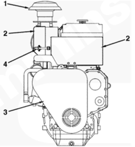
1 Air filter inlet 2 Insulation cover 3 Belt and shock absorber protection cover 4 Insulation cover joint clamp
Back view of 6BTA5.9 engine
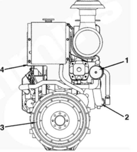
1 heat exchanger 2 heat exchanger engine coolant outlet 3 flywheel 4 expansion tank mounting bracket
side view of 6BTA5.9 engine
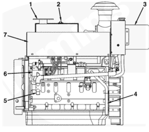
1 Exhaust port 2 Insulation cover joint clamp 3 Air filter 4 Blowby outlet pipe 5 Sea water inlet 6 Fuel pump 7 Insulation cover
6BTA5.9 Cummins Engine Exhaust Side View

1 exhaust outlet connector 2 heat shield 3 heat exchanger coolant inlet 4 oil filter 5 turbocharger oil return pipe connector 6 heat exchanger 7 heat exchanger seawater outlet
The above information is sourced from internet industry news, hereby declare! If there is any violation of relevant laws or copyright infringement, please notify us! Kind reminder: Please do not reprint information without our permission!
If you would like to learn more about the technical data and product information of diesel generator sets, please contact the sales promotion department by phone or visit our official website: www.swaflyengine.com
Previous:What does Hydraulic Pumps do?